

Fine Grinding and Dispersion of Viscous Pastes
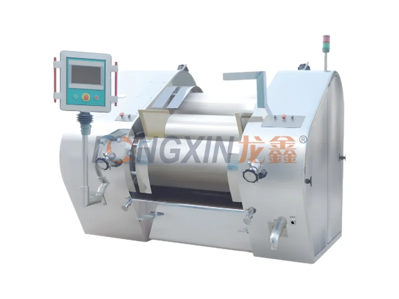
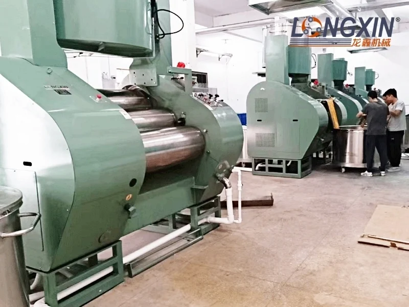
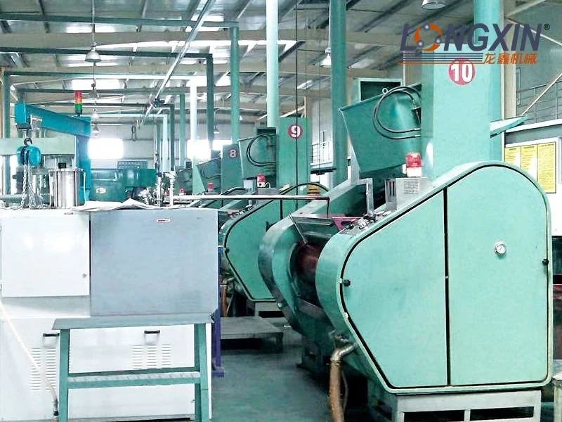
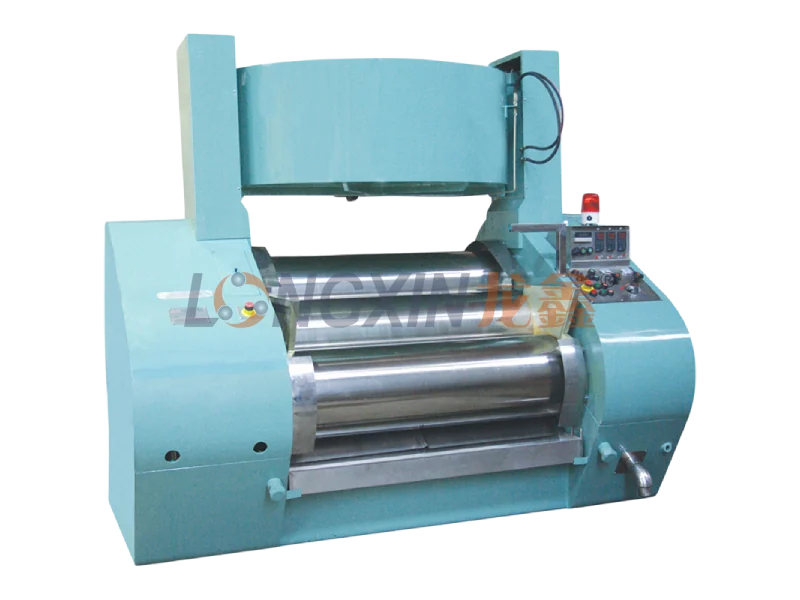
The Longxin YS–YSS fully hydraulic three-roll mill processes medium- to high-viscosity materials through controlled shear and compression between three rolls. Typical feeds include metal pastes, printing and conductive inks, adhesives, sealants and lubricating greases.
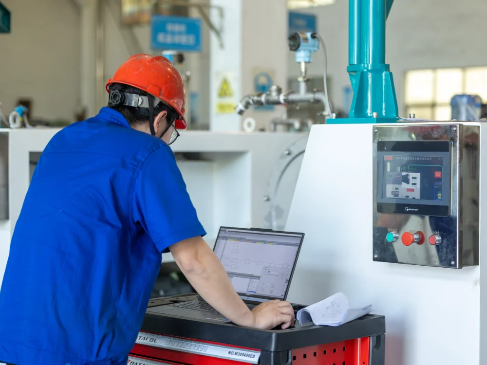
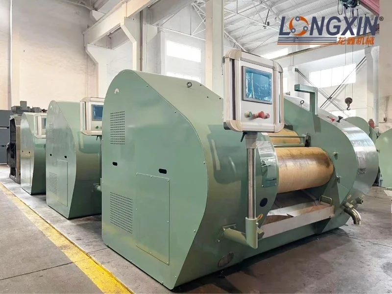
Hydraulic roll loading and adjustable process settings allow the mill to be matched to the formulation. PLC and touchscreen configurations support recipe handling, parameter monitoring and repeatable batch processing.
How the Three-Roll Mill Works
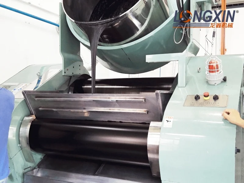
- Feed to the first nip: premixed material enters the gap between the slow feed roll and the intermediate roll.
- Initial dispersion: the rolls turn at different surface speeds. Compression and shear break down agglomerates and distribute particles through the liquid or paste phase.
- Second grinding stage: material transfers to the gap between the intermediate roll and the faster discharge roll for further dispersion and refinement.
- Controlled roll loading: hydraulic pressure maintains the selected loading between the rolls. Gap and pressure settings are adjusted for the formulation and target result.
- Product discharge: a doctor blade removes the processed material from the discharge roll and directs it into the collection tray.
Roll Control and Operating Positions
The described control configuration supports gap control, pressure control and combined gap/pressure control. Roll speed, gap and loading are selected together with cooling conditions to suit the paste viscosity and required dispersion quality.
- Grinding position: used for fine grinding and dispersion at the selected settings.
- Mixing position: provides a roll arrangement suited to the mixing stage.
- Disengaged position: separates the rolls to facilitate cleaning and access.
The stated roll line-load range is 5–120 N/mm. This is force per unit roll length; the hydraulic system pressure is specified separately in MPa in the technical table.
Precision Rolls and Cooling
Precision-machined rolls and controlled roll alignment support uniform processing across the working face. The supplied design description specifies roll cylindricity and concentricity within 2 µm. Actual product fineness depends on the formulation, roll settings and number of passes and should be established in application trials.
- Roll surfaces: premium alloy rolls are listed in the standard model schedule. Ceramic material options include zirconia, alumina, silicon carbide and silicon nitride, subject to the selected configuration.
- Temperature management: roll cooling removes heat generated during processing, helping control the temperature of sensitive formulations.
- Drive system: the motor and transmission provide the speed differential between the rolls. The reference speeds for the slow, intermediate and fast rolls are listed by model.
- Doctor blades: metal, ceramic or glass-fiber blade options can be selected for material compatibility and discharge requirements.
Feeding and Equipment Layout
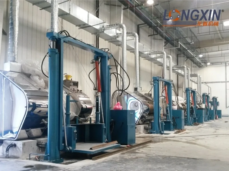
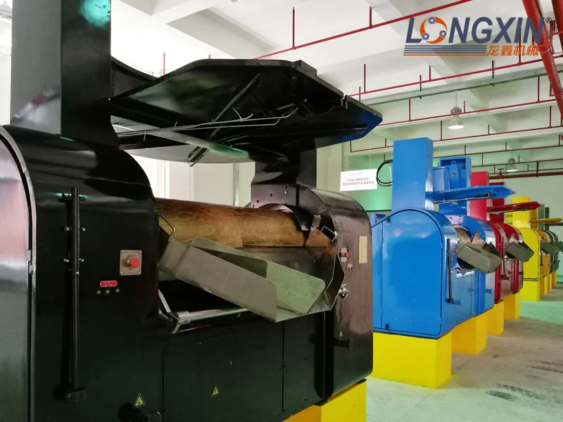
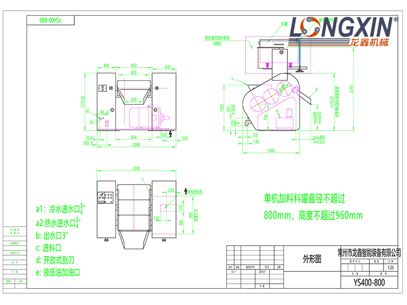
An optional feed tipper transfers viscous material from a vessel to the roll feed zone. Frame finish, feeding equipment, discharge height and installation clearances are selected around the production layout.
The YS400-800 drawing below shows an example with a feed tipper. Its dimensions include configuration-specific features; use the approved project drawing for installation and vessel-clearance checks.
Automation, Cleaning and Protective Functions
- PLC and touchscreen options: the described Siemens PLC configuration supports setting and monitoring roll speed, gap and pressure, with recipe storage and pressure-trend display.
- Production data: data collection and MES connectivity can be configured for process traceability and plant integration.
- Discharge and side-seal adjustment: self-aligning collection and roll-side sealing arrangements help contain material and reduce manual adjustment.
- Cleaning access: the cleaning configuration opens the roll gap and uses controlled low-torque operation. Cleaning must follow the supplied operating procedure.
- Protective functions: the described equipment includes motor overload protection and monitored guards and collection components. The final protective arrangement depends on the machine configuration.
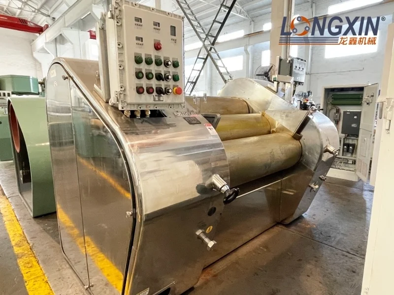
- Frame options: painted and stainless steel frames are available; cleanroom-oriented versions can be specified to suit the production environment.
Typical Applications
- Printing and UV inks: packaging inks, security inks, sheet-fed inks and web-offset inks.
- Electronic pastes: silver, aluminum, nickel, copper and platinum pastes, conductive inks and flux pastes.
- Functional materials: adhesives, sealants, lubricating greases, ceramic pastes and high-performance composite formulations.
- Cosmetics and personal care: lipstick, lip balm, lip gloss, sunscreen, foundation and hair wax formulations.
- Other viscous products: suitable coatings, pigments, color pastes, gums, soaps and grease-based materials.
Configure a Mill for Your Formulation
Provide the material composition, viscosity and processing temperature, initial dispersion condition, target fineness, required throughput and batch size. Include contact-material restrictions, cooling-water conditions, feeding and discharge requirements, and any recipe or data-integration needs. These inputs determine the roll material, model, control package and process settings.